|
|
几年前用一块带LED数显电压的自动升降压(Boost-Bucker)模块将48VDC转成12V给爱车电瓶补电时,一不小心烧死了它的电压数显部分……因为该模块的数字电压表是由单片机STM8S003F3P6和三位LED数码管(共阴极)等构成,所以单单搞一块MCU上去是万万不行的。而当时自己对STM8系列单片机的编程可以说是毫无经验的,因此只能将模块丢一边从长计议,但心中执念尚存。
説到执念,的确,俺对编程这东西甚是感兴趣,认为能编程的大拿真的很酷——一番行云流水后,硅片中注入他的思想,就像是让硅基生命顿时获得了灵魂一样。可是,俺的脑瓜子不怎么灵活,也比较懒散,羡慕他人却没那恒心。年轻时学了一阵子汇编,没继续深入,就这么荒废了;N年前,见着人家玩STM32烧录器,手痒跟进了一段时间,照猫画虎成功后热度退却也没深入,叕荒废了……
但如今为了恢复这块损坏的模块,也算是对自己的挑战吧,把STM8系列MCU开发用到的软件、硬件一一搞来,熟悉了一阵子。后来眼见自己又要打退堂鼓,暗下决心这次一定要完成任务。于是就有了这篇啰嗦文。
言归正传,在网上兜兜转转正巧找到一篇关于怎样魔改数显电压表的文章,该作者是将一块廉价4位LED数显电压表改成了电流表,该电压表也是采用STM8S003F3P6,因此程序有相当高的参考性。经过多日断断续续的研究,了解其中每一个语句的作用,了解了ADC、Timer、中断……最后慢慢调整以将其适配自己那个DC-DC模块。
时至今日,总算完成所有程序改造,基本驯服了这个小小的硅基生命体,让整个DC-DC模块重获新生。期间尽管遇到很多困难,但配合AI问答都一一解决,让自己又学到很多东西,太棒了!不得不说,如今的AI会话在编程辅助方面真得很赞。
最终的效果如下:
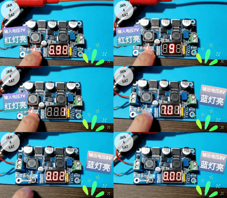
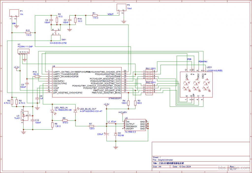
下边是它的原理图。
三位LED数码管显示双路电压部分:
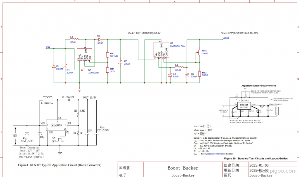
Boost-Bucker 部分:
以下是俺的程序部分:
Main.C
- #include "stm8s.h"
- #include "led.h"
- #define LED_delay (1) // one digit emitting time
- #define ADC_delay (50) // delay for reading voltage
- #define Display_delay (400) // delay for displaying value
- uint32_t Global_time = 0L; // global time in ms
- uint32_t ADC_time = 0L;
- uint32_t Display_time = 0L;
- uint8_t waitforADC = 0;
- uint8_t ADC_started = 0;
- uint16_t ADC_values[3] = { 0, 0, 0 };
- uint8_t index = 0;
- uint8_t current_channel = 1; // 0: AIN3, 1: AIN4
- void simpleDelay(uint8_t how_much);
- uint16_t adc_read(void)
- {
- uint16_t temph = 0;
- uint8_t templ = 0;
- ADC1->CR1 |= ADC1_CR1_ADON; // wake it up
- ADC1->CR1 |= ADC1_CR1_ADON; // start the conversion, wait few ms
- simpleDelay(1);
- while (!(ADC1->CSR & ADC1_CSR_EOC)); // wait for conversion to finish
- /* Read LSB first */
- templ = ADC1->DRL;
- /* Then read MSB */
- temph = ADC1->DRH;
- temph = (uint16_t)(templ | (uint16_t)(temph << (uint8_t)8));
- ADC1->CR1 &= (uint8_t)(~ADC1_CR1_ADON); // power it off
- return (uint16_t)temph;
- }
- // store ADC value in a rolling array
- void store(uint16_t value)
- {
- ADC_values[index++] = value; // store value in array
- if (index == 3) index = 0; // check index overflow
- }
- // get median value
- uint16_t median(uint16_t value1, uint16_t value2, uint16_t value3)
- {
- if ((value1 <= value2) && (value1 <= value3))
- {
- return (value2 <= value3) ? value2 : value3;
- }
- else
- {
- if ((value2 <= value1) && (value2 <= value3))
- {
- return (value1 <= value3) ? value1 : value3;
- }
- else
- {
- return (value1 <= value2) ? value1 : value2;
- }
- }
- }
- // calculate average value
- uint16_t average(uint16_t value1, uint16_t value2, uint16_t value3)
- {
- uint16_t value = 0;
- uint8_t count = 0;
- if (value1 > 0)
- {
- value += value1;
- count++;
- }
- if (value2 > 0)
- {
- value += value2;
- count++;
- }
- if (value3 > 0)
- {
- value += value3;
- count++;
- }
- if (count > 0) value /= count;
- return value;
- }
- // ADC initialization
- void ADC_init()
- {
- // Initialize ADC
- // Setup ADC on AIN6/PD6, AIN4/PD3, AIN3/PD2
- GPIOD->DDR &= (uint8_t)(0b10110011); // Set PD2/3/6 as floating input
- GPIOD->CR1 &= (uint8_t)(0b10110011);
- ADC1->CR1 &= (uint8_t)(~ADC1_CR1_CONT); // Set single conversion mode
- ADC1->CR1 &= (uint8_t)(~ADC1_CR1_SPSEL); // Clear the SPSEL bits (prescaler)
- ADC1->CR1 |= 0x40; // Select the prescaler division factor
- ADC1->CR2 |= ADC1_CR2_ALIGN; // Configure right data alignment
- ADC1->CR2 &= (uint8_t)(~ADC1_CR2_EXTTRIG); // Disable external trigger
- ADC1->CR2 &= (uint8_t)(~ADC1_CR2_EXTSEL); // Clear external trigger selection bits
- ADC1->CR2 &= (uint8_t)(~ADC1_CR2_SCAN); // Disable scan mode
- ADC1->CSR = 0x06; // Select AIN6 as initial channel
- }
- void main()
- {
- uint32_t T_LED = 0L; // time of last digit update
- uint16_t ADC_value = 0;
- uint16_t value = 0, vref = 0, value1 = 0, value2 = 0, value3 = 0;
- uint8_t i, count = 0;
- ADC_init();
- // Setup Timer1
- TIM1->PSCRH = 0;
- TIM1->PSCRL = 15; // LSB should be written last
- TIM1->ARRH = 0x03; // auto-reload each 1ms
- TIM1->ARRL = 0xE8;
- TIM1->IER = TIM1_IER_UIE;
- TIM1->CR1 = TIM1_CR1_ARPE | TIM1_CR1_URS | TIM1_CR1_CEN;
- // Configure clocking
- CLK->CKDIVR = 0; // F_HSI = 16MHz
- // Configure pins
- CFG->GCR |= 1; // disable SWIM
- LED_init();
- set_display_buf("000");
- Button_init();
- enableInterrupts();
- while (1)
- {
- if (((uint16_t)(Global_time - ADC_time) > ADC_delay) || (ADC_time > Global_time))
- {
- ADC_time = Global_time;
- // read three values and get median
- value1 = adc_read();
- value2 = adc_read();
- value3 = adc_read();
- vref = median(value1, value2, value3);
-
- if (current_channel)
- {
- ADC1->CSR = (ADC1->CSR & 0xF0) | 0x04; // select AIN4
- GPIOA->ODR &= (uint8_t)(0b11111011); // light blue LED
- }
- else
- {
- ADC1->CSR = (ADC1->CSR & 0xF0) | 0x03; // select AIN3
- GPIOA->ODR |= (uint8_t)(0x04); // light red LED
- }
-
- value1 = adc_read();
- value2 = adc_read();
- value3 = adc_read();
- value = median(value1, value2, value3);
- store(value * (long)3120 / vref); // avoid uint16_t overflow
- ADC1->CSR = 0x06; // restore AIN6 as sampling channel
- }
- if ((uint16_t)(Global_time - Display_time) > Display_delay)
- {
- Display_time = Global_time;
- value = average(ADC_values[0], ADC_values[1], ADC_values[2]);
- display_int(value, 1); // allow auto decimal point
- }
- if (Display_time > Global_time) Display_time = Global_time; // reset Display_time when Global_time overflows
-
- if ((uint8_t)(Global_time - T_LED) > LED_delay)
- {
- T_LED = Global_time;
- show_next_digit();
- }
- // used for non-blocking read
- if (ADC_started)
- {
- wait_ADC();
- }
- if (waitforADC)
- {
- ADC_value = adc_read_end();
- store(value * (long)100 * 3.3 / 1024); // store current voltage value
- waitforADC = 0;
- }
- }
- }
- // keep the processor busy for some time
- void simpleDelay(uint8_t how_much)
- {
- unsigned int i, j;
- for (i = 0; i < how_much; i++)
- {
- for (j = 0; j < 40; j++)
- {
- }
- }
- }
- // Timer1 Update/Overflow/Trigger/Break Interrupt
- INTERRUPT_HANDLER(TIM1_UPD_OVF_TRG_BRK_IRQHandler, 11)
- {
- if (TIM1->SR1 & TIM1_SR1_UIF) // update interrupt
- {
- Global_time++; // increase timer
- }
- TIM1->SR1 = 0; // clear all interrupt flags
- }
- INTERRUPT_HANDLER(EXTI_PORTA_IRQHandler, 3)
- {
- if ((GPIOA->IDR & 0x08) == 0)
- {
- // delay 2ms for debounce
- unsigned int i, j;
- for (i = 0; i < 50; i++)
- {
- for (j = 0; j < 40; j++) {}
- }
- // release detection
- while ((GPIOA->IDR & 0x08) == 0) {}
- // toggle ADC channel
- current_channel = !current_channel;
- }
- }
LED.C
- #include "stm8s.h"
- #include "led.h"
- #define GPIO_PIN3 0b00001000 // 处理小数点用到
- /*
- * ***A*** Now(Org) 0 1 2 3 4 5 6 7 8 9 A B C D E F - h
- * * * (F) PC7(PB5) 0 1 1 1 0 0 0 1 0 0 0 0 0 1 0 0 1 0
- * F B (B) PD1(PC5) 0 0 0 0 0 1 1 0 0 0 0 1 1 0 1 1 1 1
- * * * (A) PC6(PB4) 0 1 0 0 1 0 0 0 0 0 0 1 0 1 0 0 1 1
- * ***G*** (G) PB5(PC6) 1 1 0 0 0 0 0 1 0 0 0 0 1 0 0 0 0 0
- * * * (C) PB4(PC7) 0 0 1 0 0 0 0 0 0 0 0 0 1 0 1 1 1 0
- * E C (DP)PC3(PD3) 1 1 1 1 1 1 1 1 1 1 1 1 1 1 1 1 1 1
- * * * ** (D) PC4(PD2) 0 1 0 0 1 0 0 1 0 0 1 0 0 0 0 1 1 1
- * ***D*** *DP* (E) PC5(PD5) 0 1 0 1 1 1 0 1 0 1 0 0 0 0 0 0 1 0
- * **
- */
- static uint8_t display_buffer[3] = {' ', ' ', ' '}; // blank by default
- static uint8_t N_current = 0; // current digit to display
- /*
- * Number of digit on indicator with common anode
- * digits 0..2: 三个数字位PC3, PC4, PA3
- */
- #define CLEAR_CATHODES() do { GPIOD->ODR |= 0x30; GPIOA->ODR |= 0x02; } while (0) // set cathodes high
- /************* arrays for ports *************/
- // PB, mask: 0x30 (dec: 48), PB4:0x10=16, PB5:0x20=32
- #define PB_BLANK 0x30
- static uint8_t PB_bits[18] = {16, 16, 32, 48, 48, 48, 48, 16, 48, 48, 48, 48, 0, 48, 32, 32, 32, 48};
- // PC, mask: 0xF8 (dec: 248)
- #define PC_BLANK 0xF8
- static uint8_t PC_bits[18] = {240, 0, 112, 80, 128, 208, 240, 64, 240, 208, 224, 176, 240, 48, 240, 224, 0, 160};
- // PD, mask: 0x02 (dec: 2)
- #define PD_BLANK 0x02
- static uint8_t PD_bits[18] = {2, 2, 2, 2, 2, 0, 0, 2, 2, 2, 2, 0, 0, 2, 0, 0, 0, 0};
- // 新增按钮初始化
- void Button_init() {
- // 设置PA3为输入模式
- GPIOA->DDR &= ~(0b00001000); // PA3为输入
- GPIOA->CR1 |= 0b00001000; // PA3上拉输入
- GPIOA->CR2 |= 0b00001000; // PA3外部中断打开
- EXTI->CR1 |= 0b00000010; // 配置PA3为中断源,下降沿触发
- }
- /**
- * Initialize ports
- * anodes (PB4~5、PC3~7、PD1) are push-pull outputs
- * cathodes PD5、PD4、PA1 are ODouts in active mode, pullup inputs in buttons reading and floating inputs in inactive
- * PA1(DIG3), PD1|4|5(B、DIG2、DIG1), PC3|4|5|6|7(DP、D、E、A、F), PB4|5(C、G)
- */
- void LED_init() {
- GPIOB->DDR |= 0b00110000; // set output for PB4-5 anodes
- GPIOC->DDR |= 0b11111000; // set output for PC3~7 anodes
- GPIOD->DDR |= 0b00110010; // set output for PD1 anodes
- GPIOA->DDR |= 0b00000110; // set output for PA1 as DIG3 cathode
- // 共阴修改
- GPIOA->CR1 |= ~(0b00000010);
- GPIOC->CR1 |= ~(0b00000000);
- GPIOB->CR1 |= ~(0b00000000);
- GPIOD->CR1 |= ~(0b00110000); // All anodes should be push-pull
- // set anodes high
- GPIOB->ODR |= PB_BLANK;
- GPIOC->ODR |= PC_BLANK;
- GPIOD->ODR |= PD_BLANK;
- // set cathodes high
- CLEAR_CATHODES();
- }
- /*
- ********************* GPIO ********************
- * Px_ODR - Output data register bits
- * Px_IDR - Pin input values
- * Px_DDR - Data direction bits (1 - output)
- * Px_CR1 - DDR=0: 0 - floating, 1 - pull-up input; DDR=1: 0 - pseudo-open-drain, 1 - push-pull output
- * Px_CR2 - DDR=0: 0/1 - EXTI disabled/enabled; DDR=1: 0/1 - 2/10MHz
- */
- /**
- * Show next digit - function calls from main() by some system time value amount
- */
- void show_next_digit() {
- uint8_t L = display_buffer[N_current] & 0x7f;
- // first turn all off
- CLEAR_CATHODES();
- // set all cathodes high
- GPIOB->ODR &= ~PB_BLANK;
- GPIOC->ODR &= ~PC_BLANK;
- GPIOD->ODR &= ~PD_BLANK;
- if (L < 18) { // letter
- // set required anodes to high to light up the letter
- GPIOB->ODR |= PB_bits[L];
- GPIOC->ODR |= PC_bits[L];
- GPIOD->ODR |= PD_bits[L];
- }
- // display decimal point if required
- if (display_buffer[N_current] & 0x80) {
- GPIOC->ODR |= GPIO_PIN3; // 点亮小数点
- } else {
- GPIOC->ODR &= ~GPIO_PIN3; // 不要点亮小数点
- }
- // set anode up for current digit to light it up
- switch (N_current) {
- case 0:
- GPIOD->ODR &= ~(0x20); // DIG1
- break;
- case 1:
- GPIOD->ODR &= ~(0x10); // DIG2
- break;
- case 2:
- GPIOA->ODR &= ~(0x02); // DIG3
- break;
- }
- if (++N_current > 2) N_current = 0;
- }
- /**
- * fills buffer to display
- * @param str - string to display
- */
- void set_display_buf(char *str) {
- uint8_t B[3];
- signed char ch, M = 0, i;
- N_current = 0; // refresh current digit number
- // empty buffer
- for (i = 0; i < 3; i++)
- display_buffer[i] = ' '; // 三个数位缓存都显示“0”
- if (!str) return;
- i = 0;
- for ( ; (ch = *str) && (i < 3); str++) {
- M = 0;
- if (ch > '/' && ch < ':') { // digit
- M = '0';
- } else if (ch > '`' && ch < 'g') { // a..f
- M = 'a' - 10;
- } else if (ch > '@' && ch < 'G') { // A..F
- M = 'A' - 10;
- } else if (ch == '-') { // minus
- M = '-' - 16;
- } else if (ch == 'h' || ch == 'H') { // hex
- M = ch - 17;
- } else if (ch == '.') { // DP
- if (i == 0) { // word starts from '.'
- B[0] = 0xff;
- } else { // set point for previous character
- B[i - 1] |= 0x80;
- }
- continue;
- } else if (ch != ' ') { // bad character - continue
- continue;
- }
- B[i] = ch - M;
- i++;
- }
- // now make align to right
- ch = 2;
- for (M = i - 1; M > -1; M--, ch--) {
- display_buffer[ch] = B[M];
- }
- }
- /**
- * convert integer value I into string and display it
- * @param I - value to display, The second parameter "Voltmeter" determines whether to allow or not allow automatic decimal points.
- */
- void display_int(uint16_t I, char voltmeter) {
- int rem;
- uint8_t pos = 0; // DP position
- char N = 2, sign = 0, i;
- // -99 <= I <= 4000
- if (I < -99 || I > 4000) {
- set_display_buf("--E");
- return;
- }
- // prepare buffer for voltmeter's values
- if (voltmeter) {
- for (i = 0; i < 3; i++)
- display_buffer[i] = 0;
- if (I > 999) {
- if (I % 10 >= 5) {
- I = I / 10 + 1;
- } else {
- I /= 10;
- }
- pos = 1; // DP is in 2nd position
- }
- } else {
- for (i = 0; i < 3; i++)
- display_buffer[i] = ' ';
- }
- if (I == 0) { // just show zero
- display_buffer[2] = 0;
- return;
- }
- if (I < 0) {
- sign = 1;
- I *= -1;
- }
- do {
- rem = I % 10;
- display_buffer[N] = rem;
- I /= 10;
- } while (--N > -1 && I);
- if (sign && N > -1) display_buffer[N] = 16; // minus sign
- if (voltmeter) display_buffer[pos] |= 0x80; // 点亮pos位小数点
- N_current = 0;
- }
- /**
- * displays digital point at position i
- * @param i - position to display DP
- */
- void display_DP_at_pos(uint8_t i) {
- if (i > 2) return;
- display_buffer[i] |= 0x80;
- }
led.h
- #pragma once
- #ifndef __LED_H__//#ifndef是"if not defined"的简写
- /*在c语言中,对同一个变量或者函数进行多次声明是不会报错的。所以如果h文件里只是进行了声明工作,即使不使用#ifndef宏定义,一个c文件多次包含同一个h文件也不会报错。使用#ifndef可以避免下面这种错误:如果在h文件中定义了全局变量,一个c文件包含同一个h文件多次,如果不加#ifndef宏定义,会出现变量重复定义的错误;如果加了#ifndef,则不会出现这种错。*/
- #define __LED_H__
- #include "stm8s.h"
- void LED_init();
- void Button_init();//$$
- void set_display_buf(char *str);
- void show_next_digit();
- void display_int(uint16_t i, char voltmeter);
- void display_DP_at_pos(uint8_t i);
- #endif // __LED_H__
stm8_interrupt_vector.c
- /* BASIC INTERRUPT VECTOR TABLE FOR STM8 devices
- * Copyright (c) 2007 STMicroelectronics
- */
- #include "stm8s.h"
- INTERRUPT void TIM1_UPD_OVF_TRG_BRK_IRQHandler(void); /* TIM1 UPD/OVF/TRG/BRK ,“INTERRUPT”被声名为“@far @interrupt”*/
- //增加按钮中断服务程序$$
- INTERRUPT void EXTI_PORTA_IRQHandler(void);
- /*{
- //if (EXTI->SR & 0b00000001) { // 检查PA3的中断标志,STM32才有“SR”寄存器
- if((GPIOA->IDR & 0x08)==0)
- {
- unsigned int i, j;
- for(i = 0; i < 50; i ++)
- {
- for(j=0; j < 40; j ++)
- {
- }
- }
-
-
- //simpleDelay(50);延时50ms,消抖(在main.c中的函数不能用)
- if((GPIOA->IDR & 0x08)==0)//再次判断是否按下
- {
- while(!(GPIOA->IDR & 0x08))//松手检测
- {
- // 切换ADC通道
- static uint8_t current_channel = 0; // 0: AIN3, 1: AIN4
- current_channel = !current_channel;
- if (current_channel){
- // 切换到AIN4
- ADC1->CSR = (ADC1->CSR & 0xF0) | 0x04; // 选择AIN4(输出电压)
- GPIOD->ODR |= (uint8_t)(0b00000100);PA2作为输入输出电压指示(高电平/输出/绿色)
- } else {
- // 切换到AIN3
- ADC1->CSR = (ADC1->CSR & 0xF0) | 0x03; // 选择AIN3(输入电压)
- GPIOD->ODR &= (uint8_t)(0b11111011);PA2作为输入输出电压指示(低电平/输入/红色)
- }
- // 启动ADC转换
- //ADC1->CR1 |= 0x01; // 设置ADC启动位
- //EXTI->SR = 0b00000001; // 清除中断标志
- }
- }
- }
- }
- */
- typedef void @far (*interrupt_handler_t)(void);
- struct interrupt_vector {
- unsigned char interrupt_instruction;
- interrupt_handler_t interrupt_handler;
- };
- @far @interrupt void NonHandledInterrupt (void)
- {
- /* in order to detect unexpected events during development,
- it is recommended to set a breakpoint on the following instruction
- */
- return;
- }
- extern void _stext(); /* startup routine */
- struct interrupt_vector const _vectab[] = {
- {0x82, (interrupt_handler_t)_stext}, /* reset */
- {0x82, NonHandledInterrupt}, /* trap */
- {0x82, NonHandledInterrupt}, /* irq0 */
- {0x82, NonHandledInterrupt}, /* irq1 */
- {0x82, NonHandledInterrupt}, /* irq2 */
- {0x82, (interrupt_handler_t)EXTI_PORTA_IRQHandler}, /* irq3 */
- {0x82, NonHandledInterrupt}, /* irq4 */
- {0x82, NonHandledInterrupt}, /* irq5 */
- {0x82, NonHandledInterrupt}, /* irq6 */
- {0x82, NonHandledInterrupt}, /* irq7 */
- {0x82, NonHandledInterrupt}, /* irq8 */
- {0x82, NonHandledInterrupt}, /* irq9 */
- {0x82, NonHandledInterrupt}, /* irq10 */
- {0x82, (interrupt_handler_t)TIM1_UPD_OVF_TRG_BRK_IRQHandler}, /* irq11 */
- {0x82, NonHandledInterrupt}, /* irq12 */
- {0x82, NonHandledInterrupt}, /* irq13 */
- {0x82, NonHandledInterrupt}, /* irq14 */
- {0x82, NonHandledInterrupt}, /* irq15 */
- {0x82, NonHandledInterrupt}, /* irq16 */
- {0x82, NonHandledInterrupt}, /* irq17 */
- {0x82, NonHandledInterrupt}, /* irq18 */
- {0x82, NonHandledInterrupt}, /* irq19 */
- {0x82, NonHandledInterrupt}, /* irq20 */
- {0x82, NonHandledInterrupt}, /* irq21 */
- {0x82, NonHandledInterrupt}, /* irq22 */
- {0x82, NonHandledInterrupt}, /* irq23 */
- {0x82, NonHandledInterrupt}, /* irq24 */
- {0x82, NonHandledInterrupt}, /* irq25 */
- {0x82, NonHandledInterrupt}, /* irq26 */
- {0x82, NonHandledInterrupt}, /* irq27 */
- {0x82, NonHandledInterrupt}, /* irq28 */
- {0x82, NonHandledInterrupt}, /* irq29 */
- };
这DC-DC模块之所以损坏,俺也下了点功夫查找了原因。
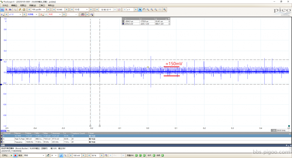
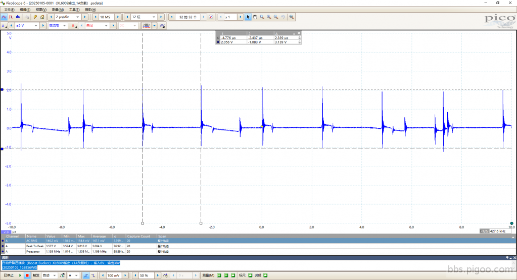
从上边的原理图中大家可以看到,数字电压表的供电由XL6009E输出的38V直流再经过Buck芯片XL1509-3.3降压后产生,而检查中发现,当生成的3.3V稍微带点负载就会让相关的这两个DC-DC芯片鬼上身,3.3V直接变≈10V的高电压,让其后边只能承受3.3V低电压的单片机重创,继而损坏XL1509-3.3。可能DC-DC电路之间存在着一些相互干扰?也可能是这个XL6009E电路输出不怎么理想的缘故——从后来的示波器查看,其38V输出在带载的情况下,显得很糟糕的样子,大家可以看下边的图。这需要接下来要去改善的地方。
而当俺把XL1509-3.3供电改成整个模块的电源输入端时,它工作得很好,即使带更大的负载也输出稳定的3.3V。这样也不错,因为在俺的使用境地,模块的输入电压不会很高,至多5.5V~12V的样子。相比38V的供电,万一XL1509-3.3损坏,高压直通低压,负载一击毙命,毫无回旋余地——这应该也是所有Buck电路的致命缺陷。
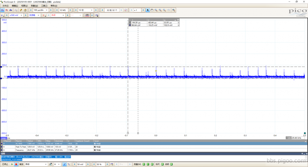
下边是示波器测到的各个输出情况(图中“1A负载”是指整个DC-DC模块输出带载)。
20250105-0001(XL6009输出_空载)
20250105-0001(XL6009输出_1A负载)
20250105-0001(LM2596S输出_空载)
20250105-0001(LM2596S输出_1A负载)
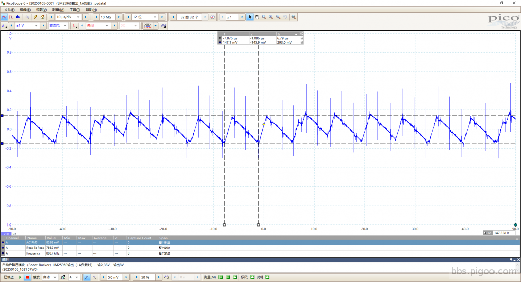
从图中可以看到,各个波形中存在很多尖峰脉冲,这是不是电压表数字跳动的元凶有待研究。
另外,我也想问问坛子里各位玩MCU的大咖,STM8S003F3P6的ADC线性是不是有问题?因为俺发现在测量个位数电压及两位数电压与实际电表测得的值相比,偏差不同。是俺程序中某些地方写得不恰当还是MCU体质就差?如何改善它呢?小弟非常期待您的答疑解惑,感恩!
谢谢各位大大的点赞,谢谢老大给予的修改机会。
|
評分
-
5
查看全部評分
-
|
