|
|
日前看到康老大的電子負載之後,想起過去做的電子負載,於是手癢享用 ARDUINO 來改寫,原因有幾個
1. ARDUINO 有 PWM 輸出功能還很方便,省去了 74hc595 加 R2R 電阻
2. I2C LCM 2004 才100元 又有程式庫方便好用
3. 愛現!
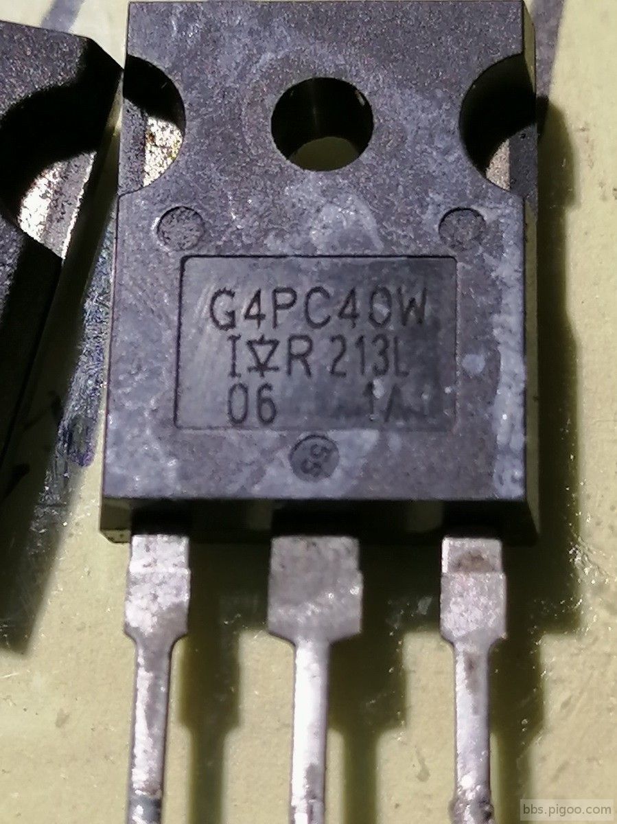
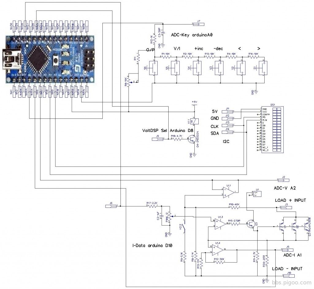
因為以前有製作的經驗,加上 功能上也可以仿用,所以就慢慢寫程式,先把 顯示部分做出來,接下來把以前的按鍵讀取功能給加進來,再把電路也加了進來,還是使用了 LM324 簡單的電路,最後把功率輸出加上去,先使用 2N3055 後來因為功率有限,所以找了一騙大一些的散熱片,翻出了 3個 IGBT 取代 2N3055 沒想到結果不理想,當初 OP 輸出接上 270歐姆 推動 2N2222A 再推2N3055 狀況良好,就是功率小了些!!
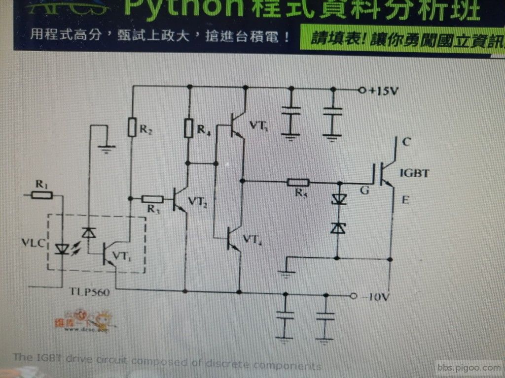
使用 IGBT 取代 2N3055 的結果,開機時候電流就飆升,過一段時間 電流降下來,還有變更電流時候,反應變的很遲緩,這應該是 IGBT 輸入端是 MOS 有電容效應,於是先把 2N2222A 去掉,用 OP 經過 270R 直推 IGBT 並且在 IGBT G極接一電阻 4.7K到地,作用於把電容效應去除(有人使用 推挽式電晶體),這結果 開機電流過大與推動反應遲緩問題就解決了!!
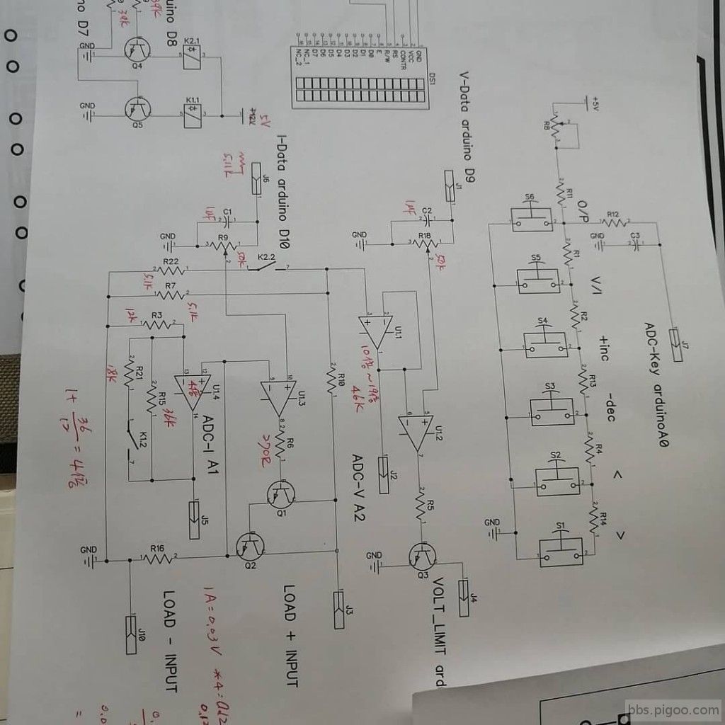
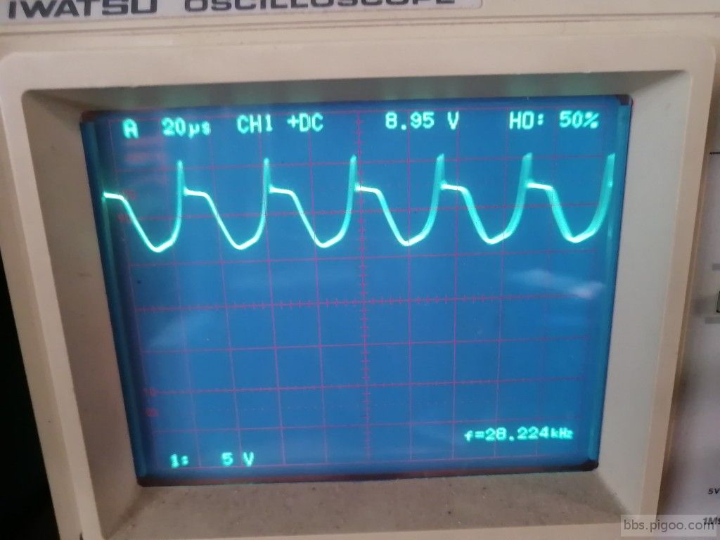
接下來發現 電壓電流讀出值顯示變動到無法讀取,依據過去的經驗,MCU讀取電壓值 ADC 經過 平均三次還會顯示跳動,那表示 直流輸出"漣波"很大,於是接上 示波器果然證明了我的判斷,當下請教 JOJOLING 大,他給我的建議是驅動電路不足,於是 把2N2222A 接上去,如圖 結果 在某一個電壓階段會發生,這一點就要 各位高手的幫忙了!!
電路設計有幾個特點:
1. 利用 繼電器(磁簧)改變輸入電壓的分壓,照樣電路可以輸入更高的電壓!!
2. 過去 設定大電流 高電壓輸出時候,會因為 瞬間功率 如: 30V 3A 一輸出電流過高會把電晶體給燒了,現在利用 PWM 一階一階的輸出,反應時間慢一點卻是保護功率晶體.
3. PWM 做 D/A 轉換 256階(8 BIT), 雖然可以做到更高階,但是我想把機會讓給別人(其實是我懶惰),ARDUINO 的 PWM 功能簡單 只要 指令analogWrite 就可以,而且一值維持輸出,但是每次更換設定就需要重新 寫上一次,這點我也沒有進一步改善(也是懶惰)
線路圖
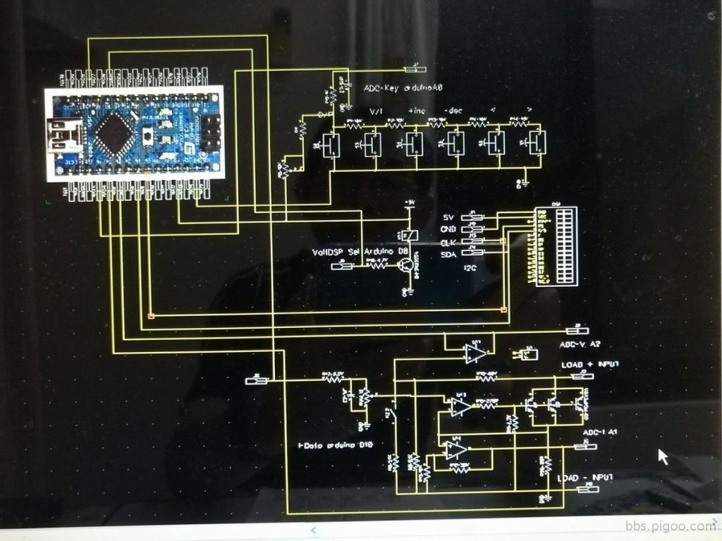
電晶體版本
IGBT 編號3個
洞洞板 和 功率晶體
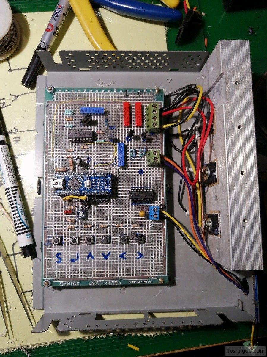
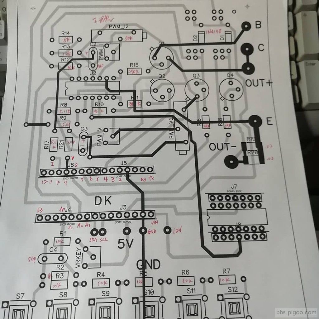
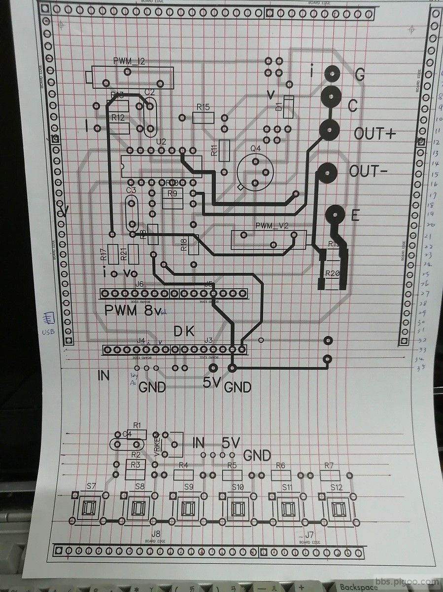
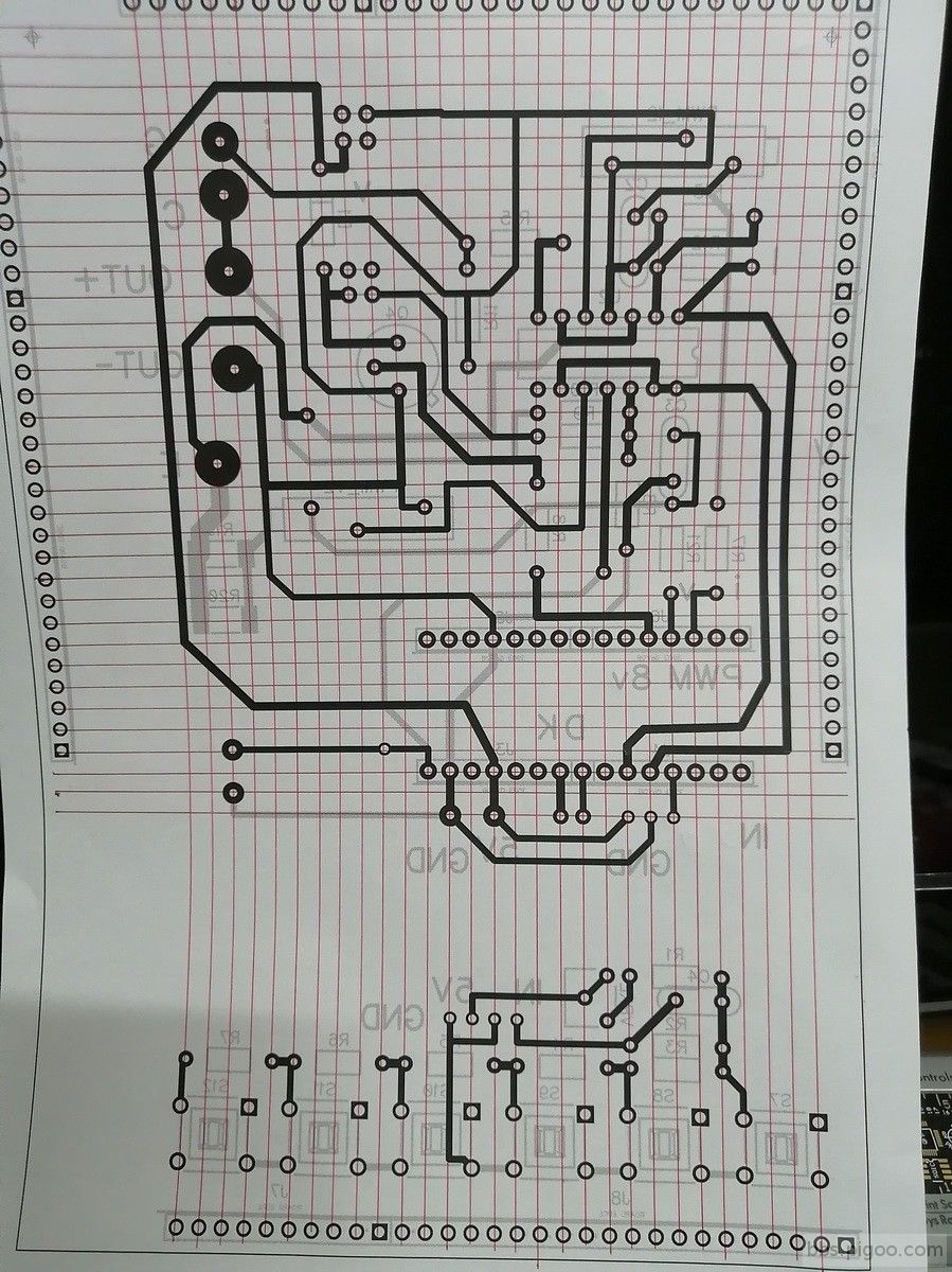
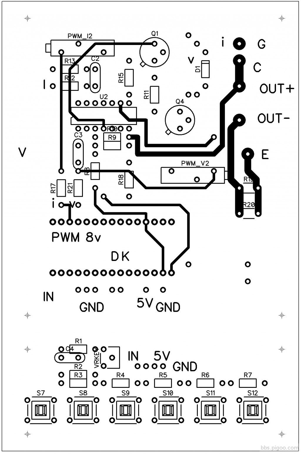
這次經驗 使用 DIPTRACE 畫好線路LAYOUT 再用紅筆劃格子,這樣元件安裝和焊接都很方便
裝上盒子 找一個SOHO 網路SWITCH,按鍵需要找長螺絲來使用
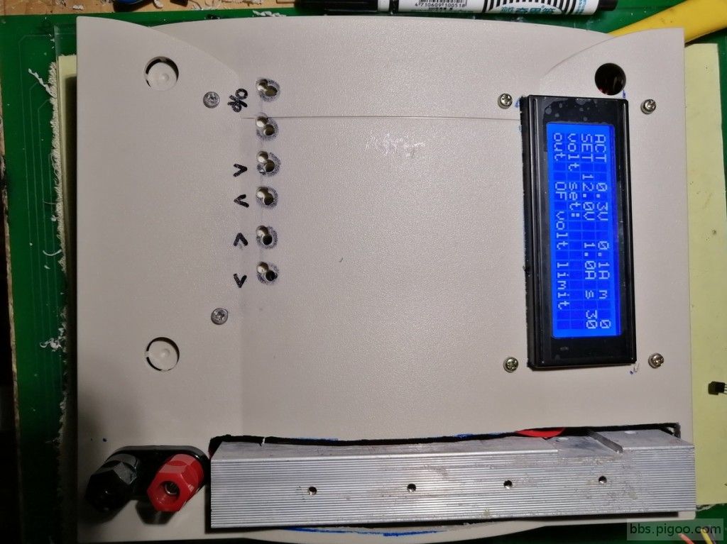
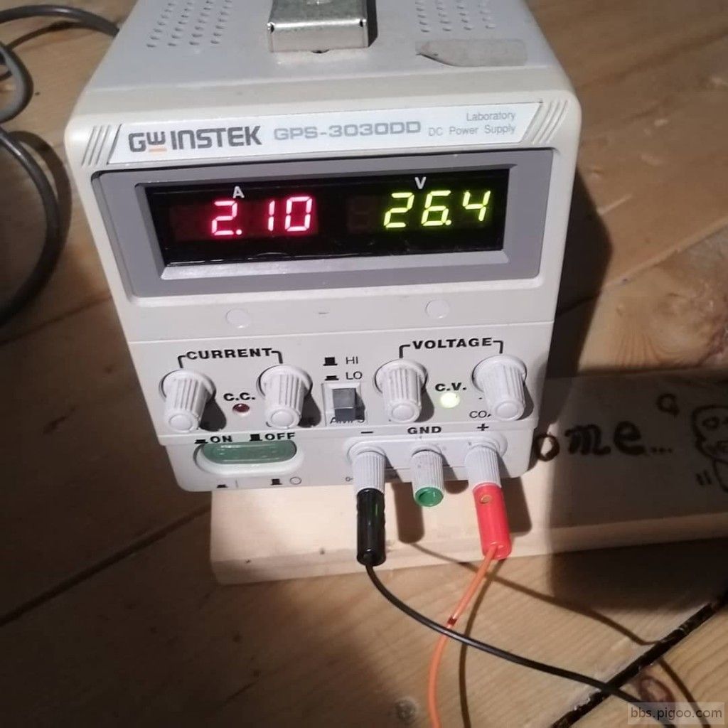
電流數據 很奇怪 IDLE 電流 100MA
電路圖
板子
網路參考的IGBT驅動線路
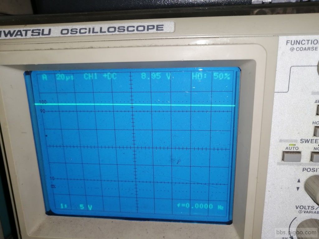
沒有負載時候電壓波形
異常電壓波形有負載超過 2A以上 (電壓不是全部範圍都會如此)
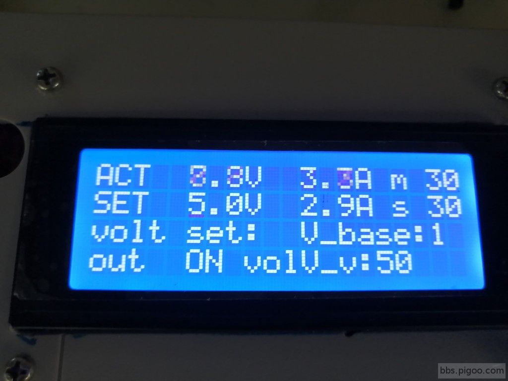
LCM 顯示現象
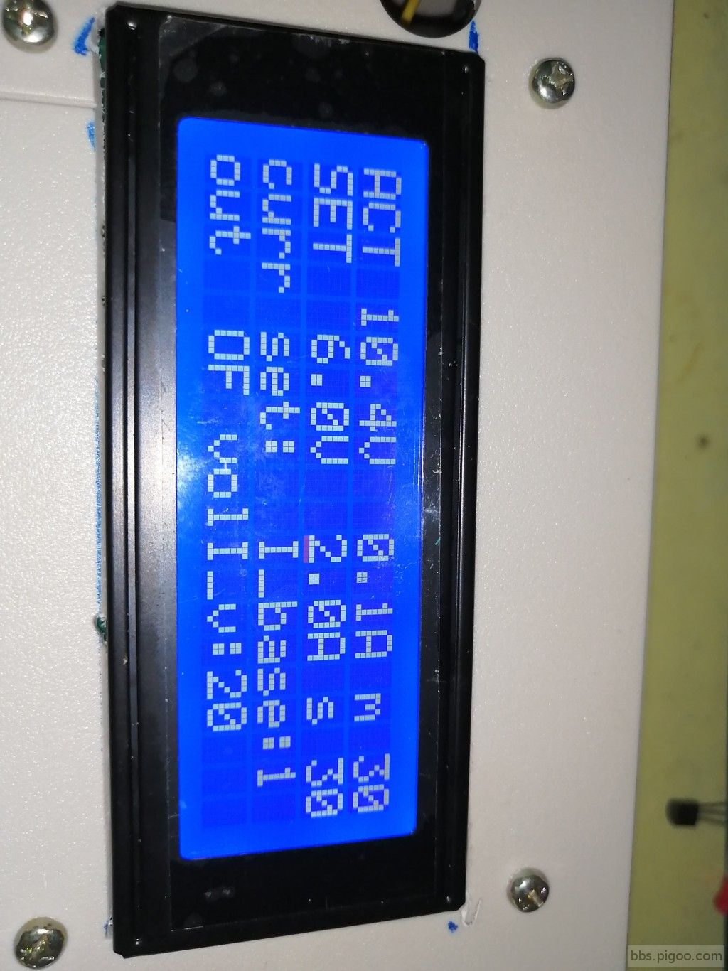
正常應該顯示狀況
I/0 輸出
S: 選擇設定 1.低電壓關閉 2.電流設定 3.時間設定
數值調整: ^ v < >
#include <Wire.h>
#include <LiquidCrystal_I2C.h>
/*digital in put D2 volt_Limit must pull up when load volt low then setting cut off out put
* digital out put D7 & D8 volt & current display gain change when high relay on volt range to 2X current gain to 1/2X
* to ADC ADC-V & ADC-I
* ADC-Keyin A0 read key board input
* ADC-V to A2 read volt data
* ADC-I to A1 read current data
* D2 volt limit input
* D7 volt gain relay out
* D8 current gain relay out
* D9 Volt PWM out
* D10 Current PWM out
*
*/
// key switch press ADC0
int KS;
int KSC;
byte Krs=0,Kls=0,Kdec=0,Kinc=0,Kenter=0,Ksel =0;
//boolean Khold = false;
//byte oldStringlength;
const int keyport = A0;
const int ADC_Vport = A2;
const int ADC_Iport = A1;
int dspKin =15;
int dspKinP=0;
byte mode = 0;//operate mode select 3mode V A T keyscan=16
byte V_value_base=1;
byte I_value_base=1;
byte T_value_base=1;
int V_value =120;//setting volt value
int I_value =10;// setting crrent value
int T_value =30;//setting timer value
int T_value_ACT;//acture time count
int V_Rvalue =0;// read volt ADC data for display
int I_Rvalue =0;// read volt ADC data for display
int V_corr =0;
String V_str;
char LCDposition[20];
float V_p;// value of float point for caculate
boolean OutPut_flag=0;//OUTPUT sw set/reset PWM output data
boolean V_sel_Relay = false;//when volt set over 40V then Relay on
boolean I_sel_Relay = false;//when current set over 40A then Relay on
byte V_o256=0;//output PWM volt
byte I_o256=0;//output PWM current
byte Vo_pin=9;//PWM V-data
byte Io_pin=10;//PWM I-data
byte V_Limit_pin =2;// discharge volt low limit set by Vo_pin
byte V_selrange_pin =8;//volt range select display
byte I_selrange_pin =7;//current range select display
long startTime = 0;//delay time
unsigned int maxTime = 60000;//60S
// 設定 LCD I2C 位址
// Set the pins on the I2C chip used for LCD connections:
// addr, en,rw,rs,d4,d5,d6,d7,bl,blpol
LiquidCrystal_I2C lcd(0x27, 2, 1, 0, 4, 5, 6, 7, 3, POSITIVE);
void setup() {
pinMode(Vo_pin,OUTPUT);
pinMode(Io_pin,OUTPUT);
pinMode(V_selrange_pin,OUTPUT);
pinMode(I_selrange_pin,OUTPUT);
pinMode(V_Limit_pin,INPUT_PULLUP);
// 初始化 LCD,一行 16 的字元,共 2 行,預設開啟背光
lcd.begin(20, 4);
Serial.begin(38400); // start the serial monitor link
// 閃爍三次
for(int i = 0; i < 1; i++) {
lcd.backlight(); // 開啟背光
delay(250);
lcd.noBacklight(); // 關閉背光
delay(250);
}
lcd.backlight();
// 輸出初始化文字
lcd.setCursor(0, 0); // 設定游標位置在第一行行首
lcd.print("ICshop&MakerPRO");
delay(1000);
lcd.setCursor(0, 1); // 設定游標位置在第二行行首
lcd.print("Hello, Maker!");
delay(1000);
lcd.clear(); //顯示清除
}
void loop() {
lcd.setCursor(0,0);
lcd.print("ACT 00.0V 00.0A m000");
lcd.setCursor(0,1);
lcd.print("SET 12.0V 1.0A s 30");
lcd.setCursor(0,2);
lcd.print("volt set:");
String aa="12.0";
aa.toCharArray(LCDposition,5);
lcd.setCursor(4,1);
lcd.print(LCDposition);
aa=" 1.0";
aa.toCharArray(LCDposition,5);
lcd.setCursor(10,1);
lcd.print(LCDposition);
while(1){
Rd_Disp_VI();//read ADC_V & ADC_I and display on line0
Check_VoltDrop();//if over limit then shut down
if(OutPut_flag == true)
{
if(millis()- startTime > maxTime)//time count finish
{
T_value_ACT --;
if(T_value_ACT ==0)
{
OutPut_flag =false;
analogWrite(Io_pin,0);
startTime = 0;//reset timer
lcd.setCursor(0,3);
lcd.print("time up ");
}
startTime = millis();
// Serial.println(T_value_ACT);
}
}
//讀取按鍵
dspKin = Keyscan();
if(mode==0)
{
if(V_value_base==0)
{lcd.setCursor(7-V_value_base,1);}
else
{lcd.setCursor(6-V_value_base,1);}
lcd.cursor();
}
else if(mode==1)
{
if(I_value_base==0)
{lcd.setCursor(13-I_value_base,1);}
else
{lcd.setCursor(12-I_value_base,1);}
lcd.cursor();
}
else
{
lcd.setCursor(19-T_value_base,1);
lcd.cursor();
}
if (dspKin != dspKinP)
{
// Serial.print("dspKin=");
// Serial.println(dspKin);
//----------------------- lcd.noCursor();
dspKinP = dspKin;
//顯示按鍵內容
delay(100);
}
//do function of key in
switch (dspKin)
{
case 16://change volt current time 3mode
mode ++;
if(mode >2){mode=0;}
lcd.setCursor(0,2);
lcd.print(" ");
lcd.setCursor(0,2);
switch(mode)
{
case 0:
lcd.print("volt set:");
lcd.setCursor(11,2);
lcd.print("V_base: ");
lcd.setCursor(11,2);
lcd.print("V_base:");
lcd.print(V_value_base);
lcd.setCursor(11,3);
lcd.print("V_v: ");
lcd.setCursor(15,3);
lcd.print(V_value);
lcd.setCursor(7,1);
lcd.cursor();
break;
case 1:
lcd.print("curr set:");
lcd.setCursor(11,2);
lcd.print("I_base: ");
lcd.setCursor(11,2);
lcd.print("I_base:");
lcd.print(I_value_base);
lcd.setCursor(11,3);
lcd.print("I_v: ");
lcd.setCursor(15,3);
lcd.print(I_value);
lcd.setCursor(13,1);
lcd.cursor();
break;
case 2:
lcd.print("timer set:");
lcd.setCursor(11,2);
lcd.print("T_base: ");
lcd.setCursor(11,2);
lcd.print("T_base:");
lcd.print(T_value_base);
lcd.setCursor(11,3);
lcd.print("T_v: ");
lcd.setCursor(15,3);
lcd.print(T_value);
lcd.setCursor(19,1);
lcd.cursor();
break;
}
break;
case 1://shift >
lcd.setCursor(11,2);
switch(mode)
{
case 0:
//lcd.print("volt set:");
if(V_value_base >0)
{ V_value_base--;}
lcd.print("V_base:");
lcd.print(V_value_base);
break;
case 1:
//lcd.print("current set:");
if(I_value_base >0)
{ I_value_base--;}
lcd.print("I_base:");
lcd.print(I_value_base);
break;
case 2:
//lcd.print("timer set:");
if(T_value_base >0)
{T_value_base--;}
lcd.print("T_base:");
lcd.print(T_value_base);
break;
}
break;
case 2://shift <
lcd.setCursor(11,2);
switch(mode)
{
case 0:
//lcd.print("volt set:");
if(V_value_base <2)
{ V_value_base++;}
lcd.print("V_base:");
lcd.print(V_value_base);
break;
case 1:
//lcd.print("current set:");
if(I_value_base <2)
{I_value_base++;}
lcd.print("I_base:");
lcd.print(I_value_base);
break;
case 2:
//lcd.print("timer set:");
if(T_value_base <2)
{ T_value_base++;}
lcd.print("T_base:");
lcd.print(T_value_base);
break;
}
break;
case 4://shift v
lcd.setCursor(11,3);
switch(mode)
{
case 0:
//lcd.print("volt set:");
V_value = V_value-pow(10,V_value_base);//V_valve-10^(0~3)
if( V_value <0)
{ V_value=0;}
lcd.print(" ");
lcd.setCursor(11,3);
lcd.print("V_v:");
lcd.print(V_value);
V_p =(float)V_value/10.0;
dtostrf(V_p,5,1,LCDposition);//-------------------
lcd.setCursor(3,1);
lcd.print(LCDposition);
break;
case 1:
//lcd.print("current set:");
I_value = I_value-pow(10,I_value_base);
if( I_value <0)
{ I_value=0;}
lcd.print(" ");
lcd.setCursor(11,3);
lcd.print("I_v:");
lcd.print(I_value);
V_p =(float)I_value/10.0;
dtostrf(V_p,5,1,LCDposition);//-------------------
lcd.setCursor(9,1);
lcd.print(LCDposition);
break;
case 2:
//lcd.print("timer set:");
T_value = T_value-pow(10,T_value_base);
if( T_value <0)
{ T_value=0;}
lcd.print(" ");
lcd.setCursor(11,3);
lcd.print("T_v:");
lcd.print(T_value);
V_p =T_value;
dtostrf(V_p,3,0,LCDposition);//-
lcd.setCursor(17,1);
lcd.print(LCDposition);
break;
}
break;
case 8://shift ^
lcd.setCursor(11,3);
switch(mode)
{
case 0:
//lcd.print("volt set:");
V_value = V_value+pow(10,V_value_base);
if( V_value >1000)
{V_value =1000;}
lcd.print(" ");
lcd.setCursor(11,3);
// lcd.blink();
lcd.print("V_v:");
lcd.print(V_value);
V_p =(float)V_value/10.0;
dtostrf(V_p,5,1,LCDposition);//-------------------
lcd.setCursor(3,1);
lcd.print(LCDposition);
break;
case 1:
//lcd.print("current set:");
I_value = I_value+pow(10,I_value_base);
if( I_value >500)
{I_value =500;} //max 500 for current limit
lcd.print(" ");
lcd.setCursor(11,3);
lcd.print("I_v:");
lcd.print(I_value);
V_p =(float)I_value/10.0;
dtostrf(V_p,5,1,LCDposition);//-------------------
lcd.setCursor(9,1);
lcd.print(LCDposition);
break;
case 2:
//lcd.print("timer set:");
T_value = T_value+pow(10,T_value_base);
if( T_value >1000)
{T_value =1000;}
lcd.print(" ");
lcd.setCursor(11,3);
lcd.print("T_v:");
lcd.print(T_value);
V_p =T_value;
dtostrf(V_p,3,0,LCDposition);//-
lcd.setCursor(17,1);
lcd.print(LCDposition);
break;
}
break;
case 32:
OutPut_flag = !OutPut_flag;
lcd.setCursor(0,3);
if(OutPut_flag== true)
{
T_value_ACT = T_value;
lcd.print("out ON");
V_o256 = map(V_value,0,1000,0,250);
I_o256 = map(I_value,0,500,0,250); //1000>>500 20190904 modify I_value max is 500
//for loop step up make ramp
analogWrite(Vo_pin,V_o256);
// Serial.println("Vo_pin,V_o256");
for (int x=0;x< I_o256;x++)
{
analogWrite(Io_pin,x);
delay(10);
}
analogWrite(Io_pin,I_o256);
// Serial.println("Io_pin,I_o256");
startTime = millis();//start timer
}
else
{
lcd.print("out OF");
analogWrite(Vo_pin,0);
analogWrite(Io_pin,0);
startTime = 0;//reset timer
T_value_ACT= T_value;
}
break;
}
}
}
/*
* read A1 ADC_I(ADC_Iport) & A2 ADC_V (ADC_Vport) and display on colume 0
* monitor Elec Load volt and current change
*/
void Rd_Disp_VI(void)
{
RelayWork();//check if relay turn on compare current and volt setting
V_Rvalue = Ravg(ADC_Vport);
I_Rvalue = Ravg(ADC_Iport);
Serial.print("V_Rvalue");
Serial.println(V_Rvalue);
//V_p =(float)(V_Rvalue/10.0);
V_p =(float)(V_Rvalue+7)/20.7;// modify for excel 20190914
if(V_sel_Relay == true)
{
V_p = V_p*1.9;
}
V_corr = V_p*10;
dtostrf(V_p,5,1,LCDposition);//-------------------
lcd.setCursor(3,0);
lcd.print(LCDposition);
// Serial.print("after relay V_Rvalue");
// Serial.println(V_Rvalue);
//------------------------------------------------------
V_p =(float)(I_Rvalue*.4+1)/10.0;// modify for excel
if(I_sel_Relay == true)// when relay on the input volt change to 1/2 then value must x2
{
V_p = V_p*2;
}
dtostrf(V_p,5,1,LCDposition);//-------------------
lcd.setCursor(9,0);
lcd.print(LCDposition);
//------------------- display timer ----------
V_p =T_value_ACT;
dtostrf(V_p,3,0,LCDposition);//-
lcd.setCursor(17,0);
lcd.print(LCDposition);
}
/*
* Key scan return 64 32 16 8 4 2 1
* KS read A0 input
* kkk out return no press is 64 1< 2> 4^ 8v 16V/I 32on/off
*/
int Keyscan(void)// There are 6 keys shiftL shiftR Up Down Enter & Select
{
int kkk;
KS = analogRead(keyport);//Read(A0); //key scan read port3
// Serial.println(KS);
if(KS >1000)//key no pressed
{ kkk = 64;
return kkk;
}
if((KS<850))// is press &&(Khold == false)
{
delay(20);
KS=Mavg();
KSC=Mavg();
// Serial.println(KS);
if(abs(KS-KSC)<10) //key press correctly
{
if((KS<850)&&(KS>770)) //790
{Krs=1;Kls=0;Kdec=0; Kinc=0;Kenter = 0; Ksel=0;
} //shift right
else if((KS<769)&&(KS>700))//747
{Krs=0;Kls=1;Kdec=0; Kinc=0;Kenter = 0; Ksel=0;} //shift left
else if((KS<700)&&(KS>600))//686
{Krs=0;Kls=0;Kdec=1; Kinc=0;Kenter = 0; Ksel=0;} //key down
else if((KS<600) &&(KS>450)) //4th key Dec press 588
{Krs=0;Kls=0;Kdec=0; Kinc=1;Kenter = 0; Ksel=0;}//key up
else if((KS<450)&&(KS>300))//5th key "VoI" press 412
{Krs=0;Kls=0;Kdec=0; Kinc=0;Kenter = 1; Ksel=0;}
else if(KS<300)// 6 th key "ON/OFF " press
{Krs=0;Kls=0;Kdec=0; Kinc=0;Kenter = 0; Ksel=1;}
// Serial.println(KS);
kkk= Krs*1+Kls*2+Kinc*8+Kdec*4+Kenter*16+Ksel*32;
// Serial.println(kkk);
while(analogRead(keyport)<1000) {} //0502 modify for wait key relaese
}
else //2 times check KS != KSC
{
kkk = 64;
}
}
delay(50);
return kkk;
}
// read times data and average 讀3次求平均值
// an for analog input no.
int Mavg(void)
{
byte at;
int M=0;
for (at=0;at<3;at++)
{
M=analogRead(keyport)+M;//analog 3 input
delay(50);
}
M=M/3;
// Serial.print("M =");
// Serial.println(M);
return M;
}
int Ravg(int VIport)// read analog port ADC_Vport ADC_Iport
{
byte at;
int M=0;
for (at=0;at<3;at++)
{
M=analogRead(VIport)+M;//analog 3 input
delay(1);
}
M=M/3;
// Serial.print("M =");
// Serial.println(M);
return M;
}
/*
* read D2 pin volt_limit from HI to LO
* delay 100ms check again if still LO
* set PWM analogWrite(Vo_pin,0);
analogWrite(Io_pin,0);
*/
void Check_VoltDrop(void)
{
/*
boolean V_limit = digitalRead(V_Limit_pin);
if (V_limit == false)
{
delay(100);
boolean V_limit2 = digitalRead(V_Limit_pin);
if(V_limit2 == V_limit) */
if(V_corr < V_value)
{
lcd.setCursor(0,3);
lcd.print("out OF volt limit");
// analogWrite(Vo_pin,0);
analogWrite(Io_pin,0);
OutPut_flag= false;
// Serial.println("volt limit");
// }
}
}
/*
* range select Relay work condition
* volt set over 40.0V then set relay ON change gain become 1/2
* current set over 40.0A then set relay ON change gain become 1/2
* and also set flag V_sel_Relay to true and reading data x 2
*/
void RelayWork(void)
{
if(V_value > 400)
{
V_sel_Relay = true;
digitalWrite (V_selrange_pin ,HIGH);
}
else
{
V_sel_Relay = false;
digitalWrite (V_selrange_pin ,LOW);
}
if(I_value > 400)
{
I_sel_Relay = true;
digitalWrite (I_selrange_pin ,HIGH);
}
else
{
I_sel_Relay = false;
digitalWrite (I_selrange_pin ,LOW);
}
}
https://www.pastiebin.com/5d81e065a61d6
|
評分
-
13
查看全部評分
-
|
