|
|
 發表於 2017-6-30 02:34:13
|
顯示全部樓層
本文章最後由 ericchou 於 2017-6-30 02:37 AM 編輯
雖然小弟不懂這些電子電路原理
但有篇網文
參考看看能不能啟發一些想法
Complete Motor guide for Robotics
H Bridge
https://i1.wp.com/diygadgets.co.za/wp-content/uploads/2015/12/FMV3MMIII3H9I99.jpg?resize=1050%2C700
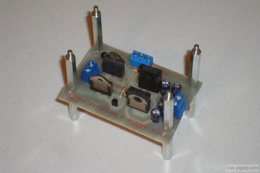
A H bridge is an electronic circuit that enables a voltage to be applied across a load in either direction. These circuits are often used in robotics and other applications to allow DC motors to run forwards and backwards.
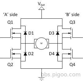
An H-bridge is a transistor-based circuit capable of driving motors both clockwise and counter-clockwise. It’s an incredibly popular circuit – the driving force behind countless robots that must be able to move both forward and backward. Fundamentally, an H-bridge is a combination of four transistors with two inputs lines and two outputs Note: there’s usually quite a bit more to a well-designed H-bridge including flyback diodes, base resistors and Schmidt triggers.) Note: there’s usually quite a bit more to a well-designed H-bridge including flyback diodes, base resistors and Schmidt triggers.)
To understand this, the H-bridge must be broken into its two sides, or half-bridges. Referring to Q1 and Q2 make up one half-bridge while Q3 and Q4 make up the other half-bridge.
https://i2.wp.com/www.instructables.com/files/deriv/FZ0/KZET/II3H9UZ7/FZ0KZETII3H9UZ7.LARGE.jpg?w=1050
Each of these half-bridges is able to switch one side of the BDC motor to the potential of the supply voltage or ground. When Q1 is turned on and Q2 is off, for instance, the left side of the motor will be at the potential of the supply voltage. Turning on Q4 and leaving Q3 off will ground the opposite side of the motor. The switching elements (Q1..Q4) are usually bi-polar or FET transistors, in some high-voltage applications IGBTs.
Note the diodes across each of the transistor (D1-D4).
These diodes protect the transistors from current spikes generated by BEMF when the transistors are switched off. The top-end of the bridge is connected to a power supply (battery for example) and the bottom-end is grounded.
A capacitor can be used with parallel to the diode. But it is optional. The value of these capacitors is generally in the 10 pF range. The purpose of these capacitors is to reduce the RF radiation that is produced by the arching of the commutators.
https://i0.wp.com/www.instructables.com/files/deriv/FIF/12DI/II3H9W09/FIF12DIII3H9W09.LARGE.jpg?w=1050
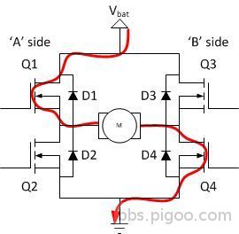
The basic operating mode of an H-bridge is fairly simple: if Q1 and Q4 are turned on, the left lead of the motor will be connected to the power supply, while the right lead is connected to ground. Current starts flowing through the motor which energizes the motor in (let’s say) the forward direction and the motor shaft starts spinning.
https://i0.wp.com/www.instructables.com/files/deriv/F1E/OGP0/II3H9W18/F1EOGP0II3H9W18.LARGE.jpg?w=1050
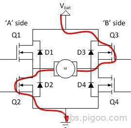
If Q2 and Q3 are turned on, the reverse will happen, the motor gets energized in the reverse direction, and the shaft will start spinning backwards.
https://i1.wp.com/www.instructables.com/files/deriv/FM5/ULOO/II3H9W1C/FM5ULOOII3H9W1C.LARGE.jpg?w=1050
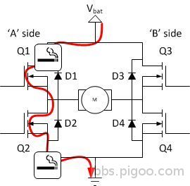
In a bridge, you should never ever close both Q1 and Q2 (or Q3 and Q4) at the same time. If you did that, you just have created a really low-resistance path between power and GND, effectively short-circuiting your power supply. This condition is called ‘shoot-through’ and is an almost guaranteed way to quickly destroy your bridge, or something else in your circuit.
There are many different models and brands of H-Bridge IC is available. Most commonly used are Texas Instruments L293NE or a Texas Instruments SN754410 and L298 from STMicroelectronics.
L293D
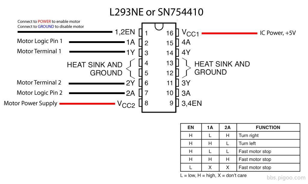
The L293NE/SN754410 is a very basic H-bridge. It has two bridges, one on the left side of the chip and one on the right, and can control 2 motors. It can drive up to 1 amp of current, and operate between 4.5V and 36V. The small DC motor generally used in robot bots can run safely off a low voltage so this H-bridge will work just fine.
The H-bridge has the following pins and features:
- Pin 1 (1,2EN) enables and disables our motor whether it is give HIGH or LOW
- Pin 2 (1A) is a logic pin for our motor (input is either HIGH or LOW)
- Pin 3 (1Y) is for one of the motor terminals
- Pin 4-5 are for ground
- Pin 6 (2Y) is for the other motor terminal
- Pin 7 (2A) is a logic pin for our motor (input is either HIGH or LOW)
- Pin 8 (VCC2) is the power supply for our motor, this should be given the rated voltage of your motor
- Pin 9-11 are unconnected as you are only using one motor in this lab
- Pin 12-13 are for ground
- Pin 14-15 are unconnected
- Pin 16 (VCC1) is connected to 5V Below is a diagram of the H-bridge and which pins do what in our example.
- Included with the diagram is a truth table indicating how the motor will function according to the state of the logic pins (which are set by our Arduino).
https://i0.wp.com/www.instructables.com/files/deriv/FKY/AGCG/II4UEF7G/FKYAGCGII4UEF7G.LARGE.jpg?w=1050
Bear in mind that all motors are available in different sizes.
Small motors are engineered for applications where compactness is valued over torque. While there are small high-torque motors, these tend to be expensive because they use rare earth magnets, high efficiency bearings, and other features that add to their cost.Large motors may produce more torque, but also require higher currents. High current motors require larger capacity batteries, and bigger control circuits that won’t overheat and burn out under the load. Therefore, match the size of the motor with the rest of the robot. Don’t overload a small robot with a large motor when big size isn’t important.When decided on the size of the motor, compare available torque after any gear reduction. Gear reduction always increases torque. The increase in torque is proportional to the amount of gear reduction: if the reduction is 3:1, the torque is increased by about three times (but not quite, because of frictional losses).
For H-bridge IC and module please visit :
|
|
 /1
/1 